OptiCan Pin Layout: Unterschied zwischen den Versionen
Aus OBD Technik Wiki
(Die Seite wurde neu angelegt: „Kategorie:Stecker+Kabel <gallery> Bild:OBD2_Pinbelegung.jpg|OptiCan Pinbelegung </gallery> <br> <div style="float:left; margin-right:1em;"> {| class="w…“) |
Admin (Diskussion | Beiträge) |
||
| Zeile 1: | Zeile 1: | ||
| − | [[Kategorie:Stecker | + | [[Kategorie:Stecker Kabel]] |
<gallery> | <gallery> | ||
Aktuelle Version vom 11. März 2014, 12:23 Uhr
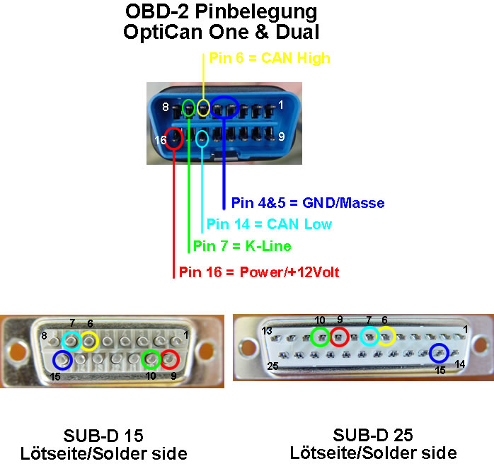
OptiCan Pinbelegung

| Beschreibung |
| OBD-2 Stecker |
|---|
| Pin 01 |
| Pin 02 |
| Pin 03 |
| Pin 04 - Fahrzeug GND |
| Pin 05 - Signal GND |
| Pin 06 - CAN High |
| Pin 07 - K-Line |
| Pin 08 |
| Pin 09 |
| Pin 10 |
| Pin 11 |
| Pin 12 |
| Pin 13 |
| Pin 14 - CAN Low |
| Pin 15 |
| Pin 16 - +12Volt |
| OptiCan One | OptiCan Dual I+II |
| SUB-D 15 | SUB-D 25 |
|---|---|
| - | - |
| - | - |
| - | - |
| 15 Pin | 15 Pin |
| 15 Pin | 15 Pin |
| 6 Pin | 6 Pin |
| 10 Pin | 10 Pin |
| - | - |
| - | - |
| - | - |
| - | - |
| - | - |
| - | - |
| 7 Pin | 7 Pin |
| - | - |
| 9 Pin | 9 Pin |